

Injection & sprays
Injection and sprays analysis and optimization for Clean Mobility and Sustainable Energy Solutions
The Injection and Sprays group at CMT develops basic research studies to improve understanding of the relevant physical processes involved, applied studies to improve engine behaviour and aid engine development including Diesel common rail, GDI fuel injection systems, hybrid vehicles as well as the spray characterization of synthetic fuels and carbon neutral fuels by means of methodologies combining experimental approach on simplified test rigs and theoretical and computational approaches at different levels of complexity.
Fuel Injection Systems: Injection rate analysis and Modelling
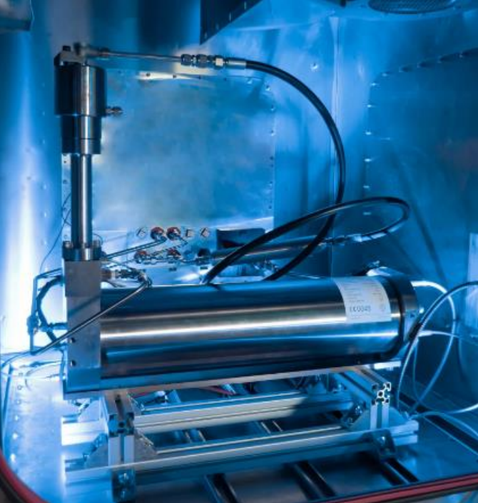
Main features:
- 5 independent EVI and 1 EMI devices are available
- In-house developed software to obtain the injection rate shape
- Simultaneous mass flow measurement to validate the results with estimated speed of sound
- Injection control devices for Bosch, BorgWarner, L'Orange, OMT fuel injection systems (piezo and solenoid)
- Controllable discharge pressure up to 180 bar to simulate engine conditions
- Experience with H2-ICE
Objectives
- Rapid determination of injection rate
- Search of injection system configuration for injection system behaviour improvement
- Influence of fuel properties on injection rate (biodiesel vs std diesel)
- Influence of temperature on dynamic behaviour
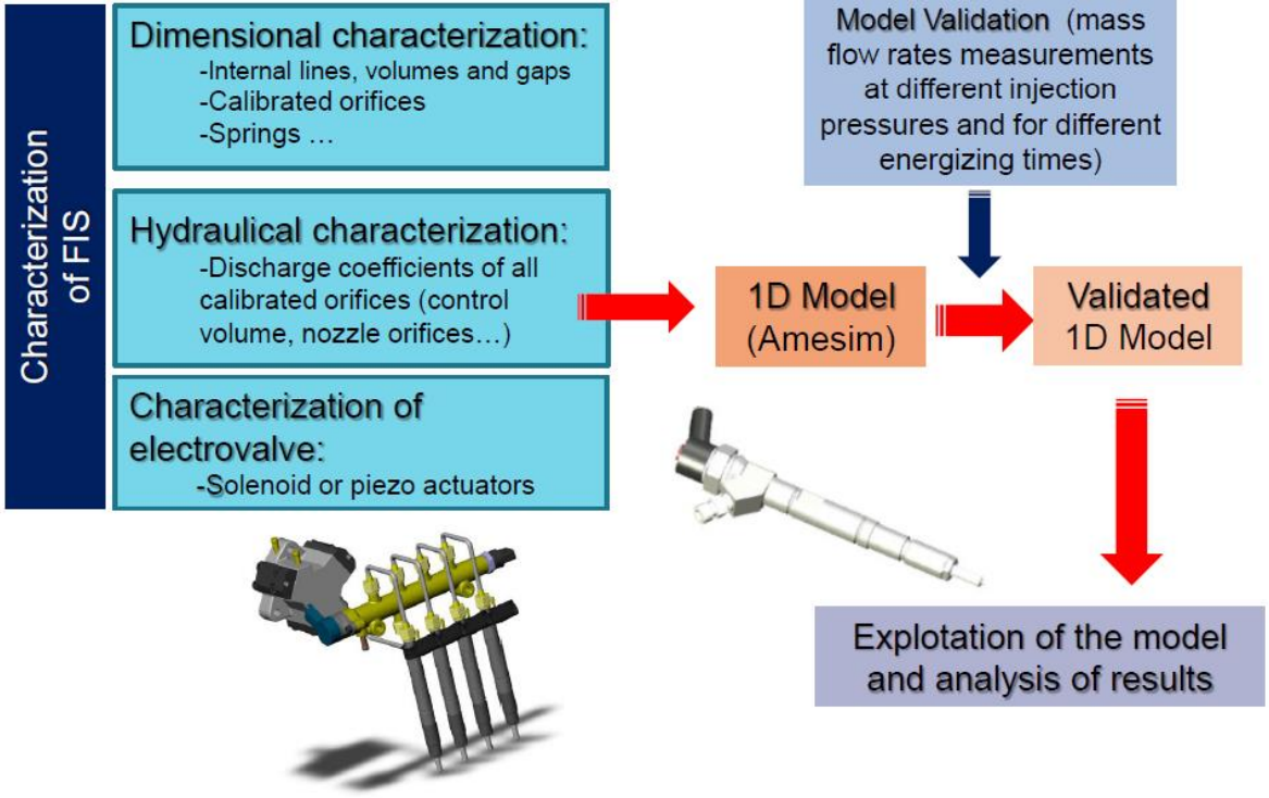
Main Features
- One-dimensional unsteady model solving the mass and momentum conservation equations. (AMEsim, Flowmaster, GT-Suite)
- Validation of each of the parts of the injection system and all the system
- Modular structure to build any injection system (line pump, rotative pump, common rail, injector nozzle, injector body, pressure regulator...)
- It calculates the unsteady fluid-mechanics and dynamic behaviour
- Applicable to either standard solenoid-operated injectors or last generation piezo-operated injectors
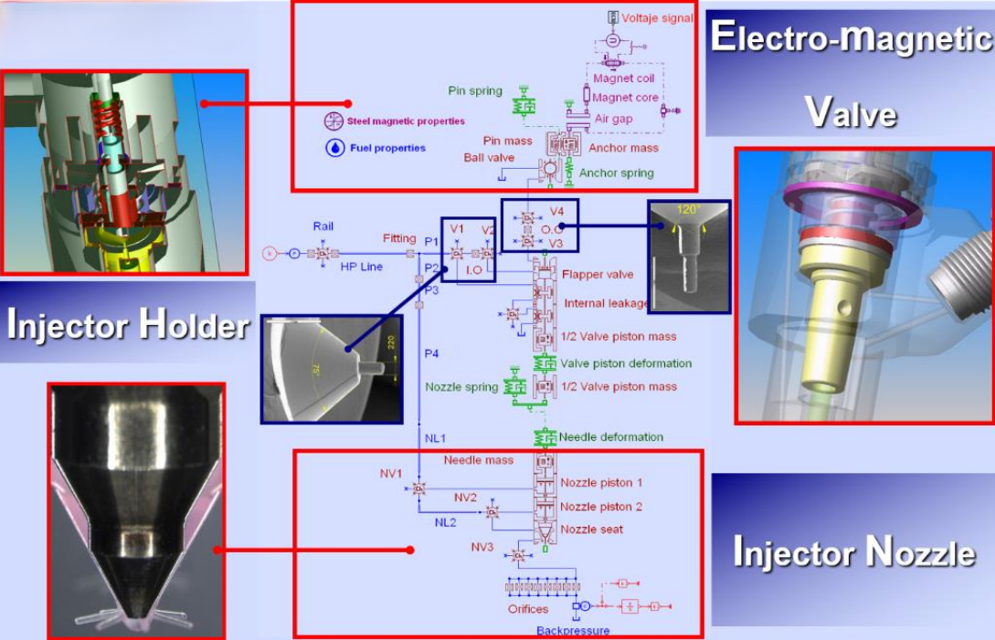
Example of 1D modelling of a solenoid injector using Simcenter Amesim code
- Electrovalve, Injector holder and injector nozzles 1D-modelling approach using elements of Simcenter Amesim from different libraries: control, hydraulics, mechanics,etc
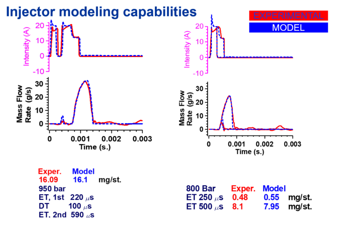
Example of results
- Comparison between an experimental mass flow rate and that obtained with the Amesim model once has been build and calibrated.
- The model results are highly reliable even for very small injection pulses affected by injector dynamics
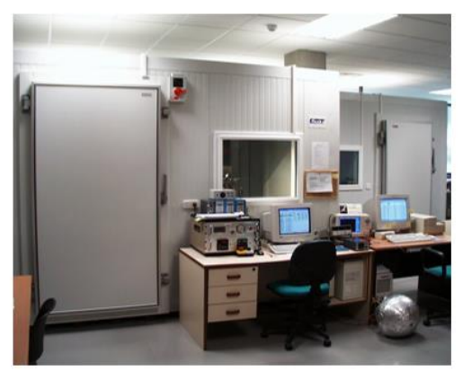
Objective:
- Temperature controlled atmosphere (Up to -30 ºC) and low relative humidity
Posible studies:
- Stability test
- Engine warm up test
- Optimization of Injection strategies for cold climates
- Influence of temperature on injection rate
- Fuel behaviour under cold and hot conditions (bio-fuels)
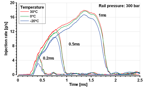
Example of results
- Influence of temperature on injection rate at -20ºC, 0ºC, and 30ºC
- Temperature strongly affects fuel viscosity, which in turn affects injector dynamics and ultimately the injection rate
Nozzle Technology
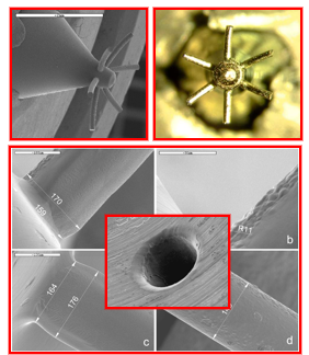
Main chracteristics
- A special silicone is introduced inside the Diesel nozzle in order to obtain the internal characteristics
- The silicone mould is taken out and analysed in an electron microscope
- Accurate and necessary information in order to perform any analysis on Diesel nozzles
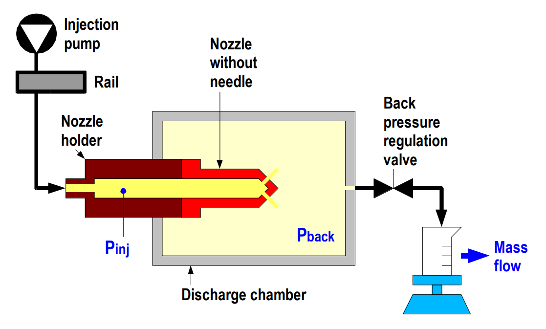
Main Characteristics
- Modification of the injector holder. No needle
- Constant inlet and outlet pressure conditions
- Continuous mass flow
- A commercial CR system is used
- It is possible to characterize any type of nozzle from any supplier
Objectives
- Detailed 3D flow modelling
- Analysis of nozzle flow characteristics and cavitation phenomenom
- Correlate orifice permeability with internal flow
- Correlate with spray behaviour, mainly atomization and air entrainment
Main features
- Simultaneous resolution of all conservative equations
- Selectable algorithms with different time/space discretization order
- Cavitation sub-model
Example of results
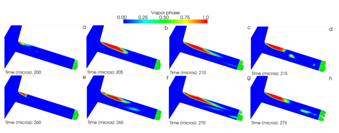
- Large Eddy Simulation (LES) for the study of gasoline jet injection with a flash-boiling sub-model
- The use of Large Eddy Simulation allows to study the turbulence development and its interaction with the flashboiling phenomenon and opening/closing transients
- The image shows different spray evolution times after the start of injection (SOI)
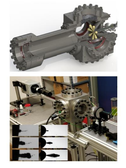
Spray initial characteristics
Main features
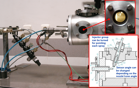
- Piezo-electric sensor. Force sensor witch directly measures the momentum flux
- Pressurized with Nitrogen
- Maximum pressure inside the chamber 100 bar
- Continuous fuel evacuation system
- Characterization of multihole nozzle: Hole to hole vaiations are evaluated
Examples of results
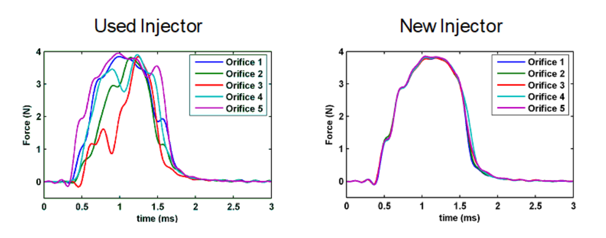
- Comparison of dispersion in momentum flux measurement between orifices in a used nozzle versus a new nozzle
- Deposits of soot and other additive particles from fuel and/or oil cause dispersion in the captured signal
- In the new nozzle, deviations between orifices in the manufacturing process and, especially, the hydro-grinding process itself generate a small dispersion in the momentum flux measurement captured downstream of the spray
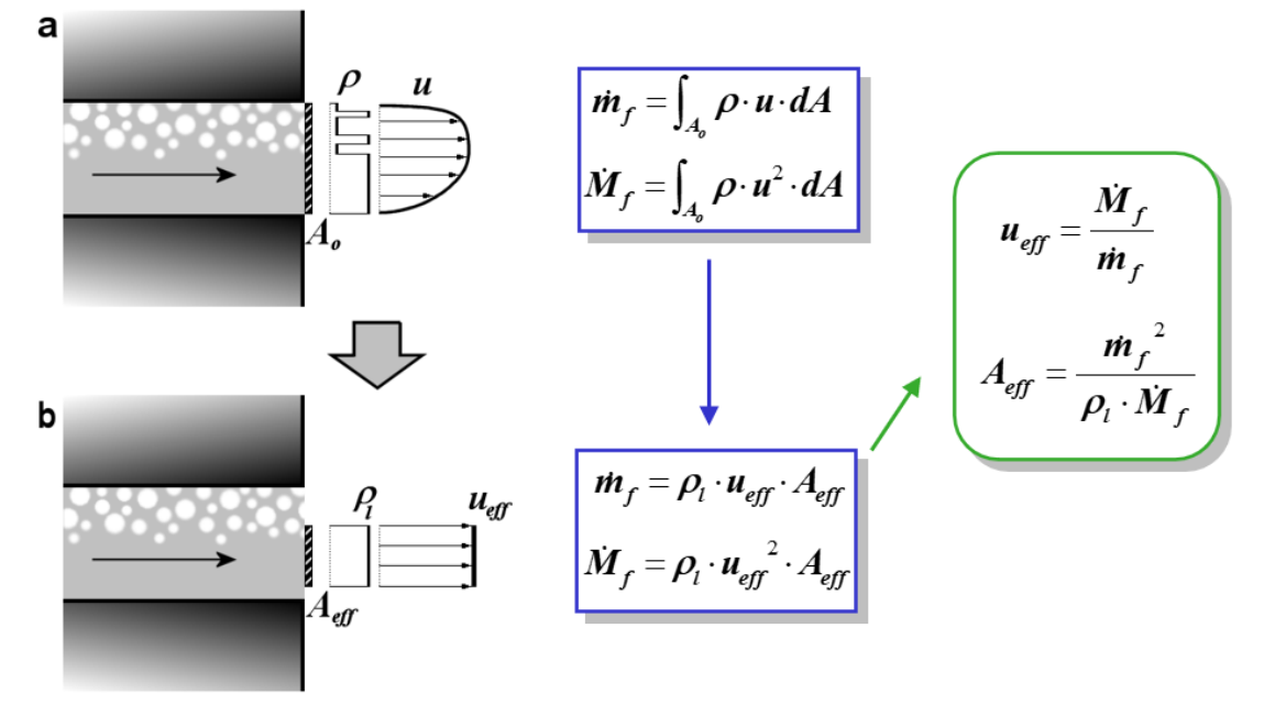
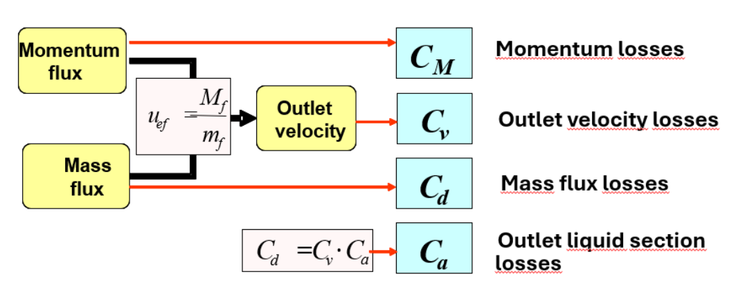
Procedure
- Outlet velocity can be estimated by means of the combination of momentum flux and the mass flux
- Coefficients: real value divided by the theoretical value
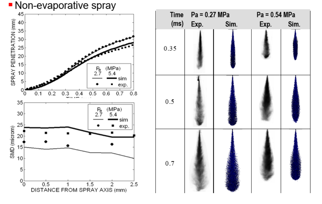
Spray Development in isothermal non-evaporative conditions
Main features:
- Gas: N2
- Pressure: 20-60 bar
- Isothermal conditions
- Test frequency < 1 Hz
- Pulse generator to operate the injector
Possible measurements
- Spray visualization for multi-hole nozzles
- Microscopic visualization of the start of injection process
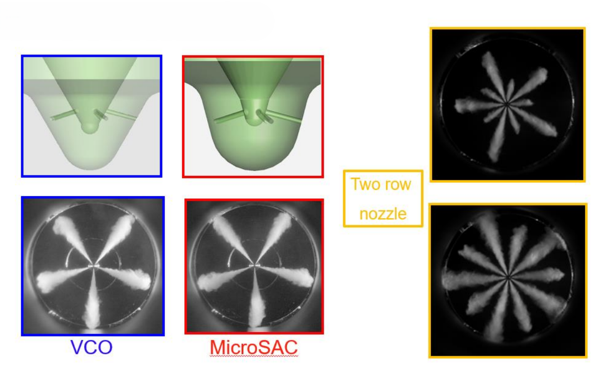
Application example
- Comparison of the morphology and macroscopic aspects of the spray from a VCO nozzle versus a micro-sac nozzle
- This vessel and optical technique enable the visualization of the spray in the near field of the nozzle (field of approximately 2mm)
- Automatic system, that includes illumination, focal lens and automatic coordinate system
- Pulsed Nd-Yag Laser with a light diffuser
- High spatial resolution (up to 250 pixels/mm)
Application example
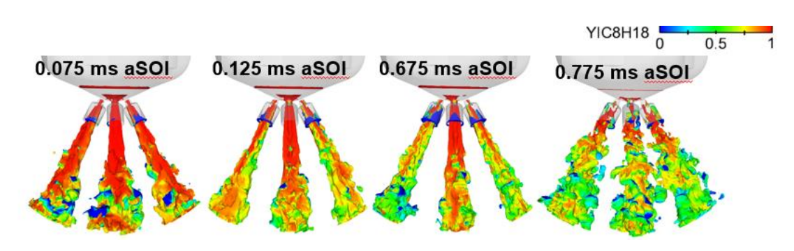
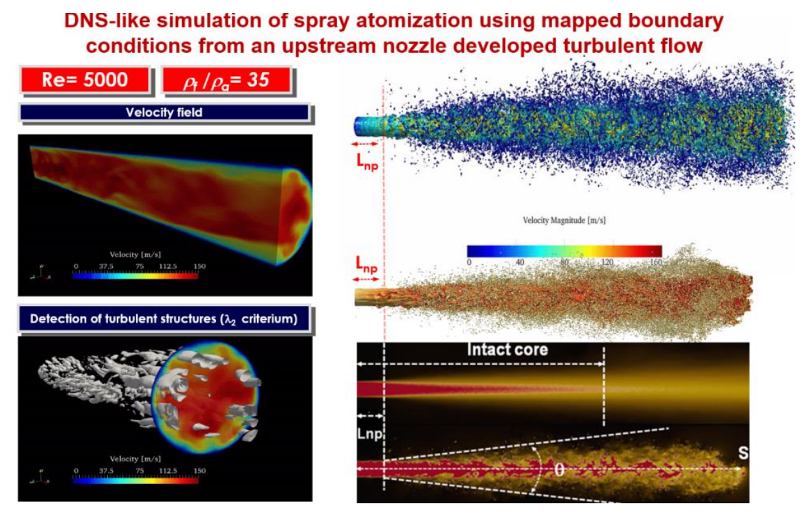
- Direct Numerical Simulation of a free spray of dodecane injected at 100 m/s into ambient air
- Mesh size of around 700 million cell with a cell size of 2 micrometers simulated on the Marenostrum 5 supercomputer at Barcelona Supercomputing Center (BSC) of the RES (Spanish Supercomputing Network)
- To take into account turbulence in the nozzle, a Large Eddy Simulation (LES) simulation has been mapped as boundary conditions at the domain inlet (nozzle outlet)
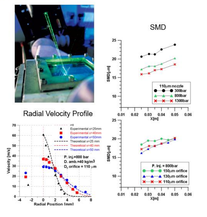
New PDA processor by DANTEC
- Phase Doppler signal processor: BSA F/P 800
- Maximum sampling frequency: 600MHz
- Maximum processable frequency: 200MHz
- Minimum transit time:42 ns
- Velocity range: -30 to +300 m/s
- Diameter range: 0.5 to 200 μm
- Measurement limit on-axis: 20 mm from orifice, function of orifice diameter, injection pressure and ambient density
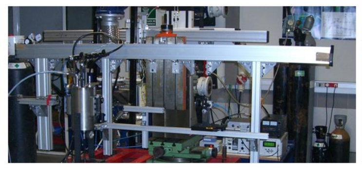
Spray evaporation and mixing
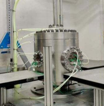
High Pressure and High Temperature Test Rigs with optical Access. Two facilities IAPAT 1 and IAPAT 2 which differ in size and maximum chamber temperature (1000K vs. 1100K)
- Used for experimental study of the injection-combustion behaviour
- Large range of controlled thermodynamic conditions including those typical of engine: (10 < P < 150 bar, 300 < T < 1000K)
- Possibility to use different fuel injection systems (any spplier)
- Possibility to use different fuels (Diesel, biodiesel, gasoline, ethanol, natural gas, OMEx, Methanol, H2, NH3, etc
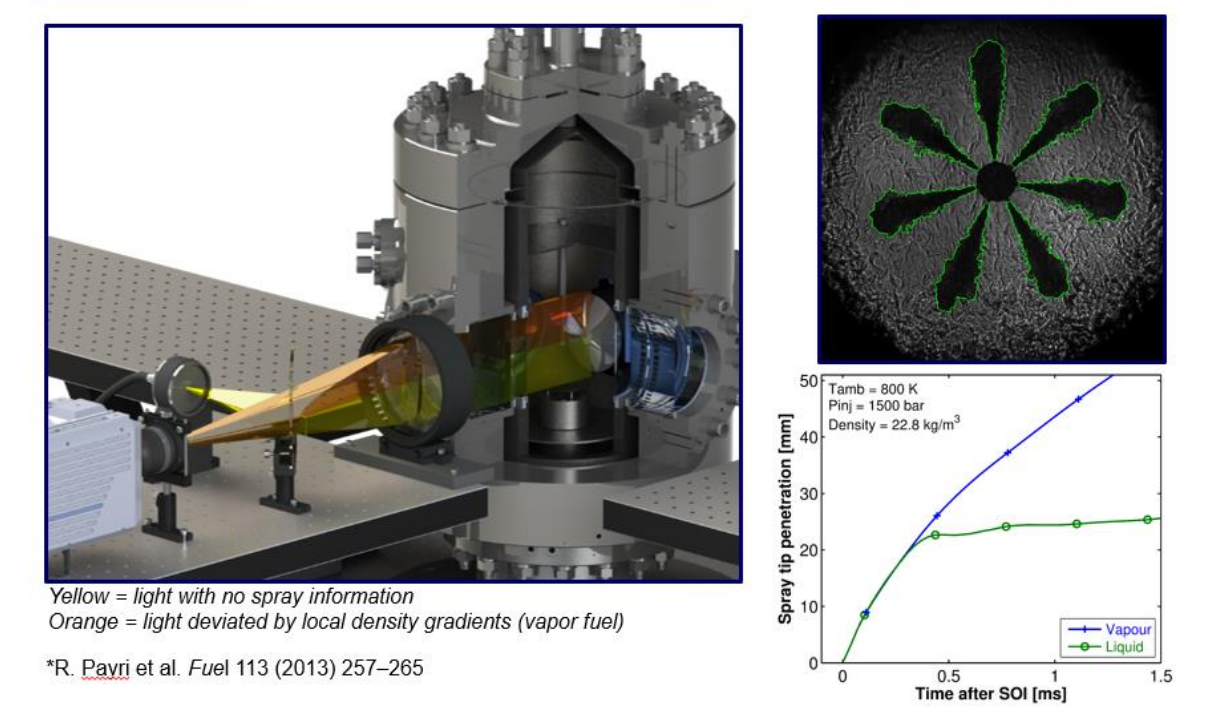
Setup and obtained results sample
- Optical arrangement for Schlieren technique, with an example image obtained at a specific moment in time, representative of vapor penetration
- The figure below on the right shows a comparison of liquid penetration obtained using the diffusive back illumination (DBI) technique and vapor penetration obtained using Schlieren
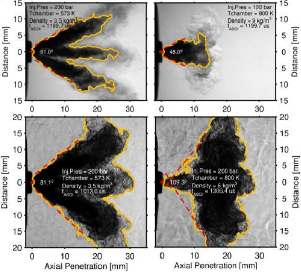
Study of flash boiling in GDI injectors using the Schlieren technique
- Example of spray morphology for different injection pressure conditions and thermodynamic conditions in the chamber using diffusive back-illumination (DBI) (two images at the top) and Schlieren technique (two images at the bottom)
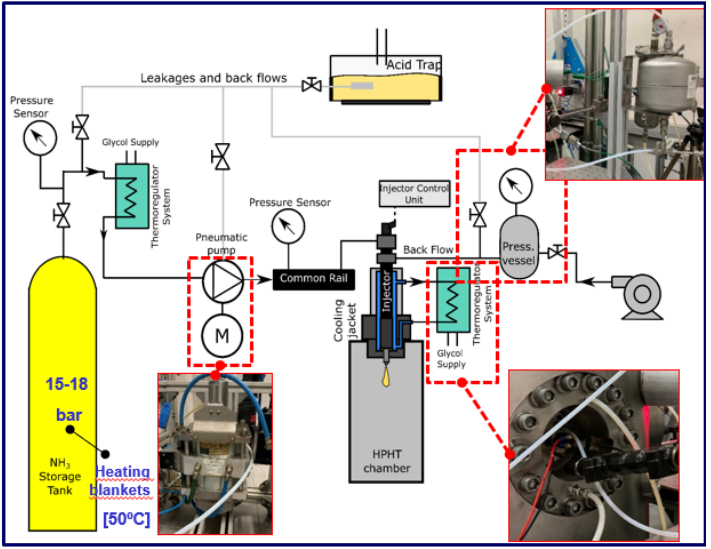
Facility for studying ammonia injection-combustion in high-power engine injectors
- Liquid ammonia is supplied from a storage tank -> NH3 cooled down to prevent cavitation in the pump
- A pneumatuc pump is used
- To prevent phase change in the injector
- All the return lines are collected -> acid trap
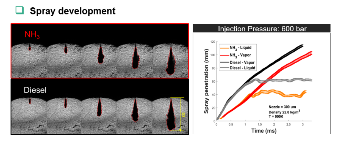
Comparative study of diesel and ammonia sprays using DBI and Schlieren techniques to determine liquid and vapor penetration
- Spray penetration results showed significant differences between NH3 and conventional diesel (used as reference), especially in the transient phase of the process
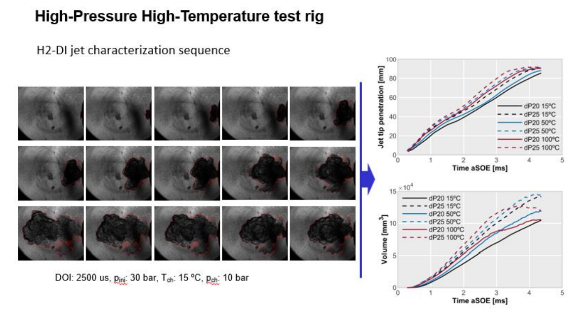
Characterization of hydrogen jet as a function of time for different temperatures
- Temperature has a significant effect on both penetration and jet volume
Reactive sprays characterization: Combustion analysis
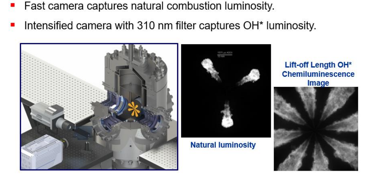
Natural luminosity and OH* radicals chemiluminescence
- Fast camera captures natural combustion luminosity
- Intensified camera with 310 nm filter captures OH* luminosity
- Examples of images captured by the cameras used in both techniques are shown on the right
Main characteristics:
- OME: mix of OME3 to OME3
- No carbon-to-carbon bonds -> No direct formation of soot precursos
- High molecular oxygen content -> Rapid oxidation
- High reactivity fuel is suitable for combustion modes based on autoignition
- Challenges -> Lower Heating Value and viscosity
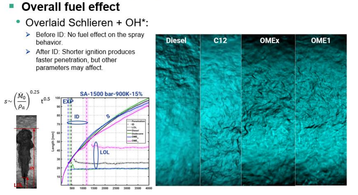
Overlaid Schlieren + OH*:
- Before ID: No fuel effect on spray behavior
- After ID: Shorter ignition produces faster penetration, but other parameters may affect
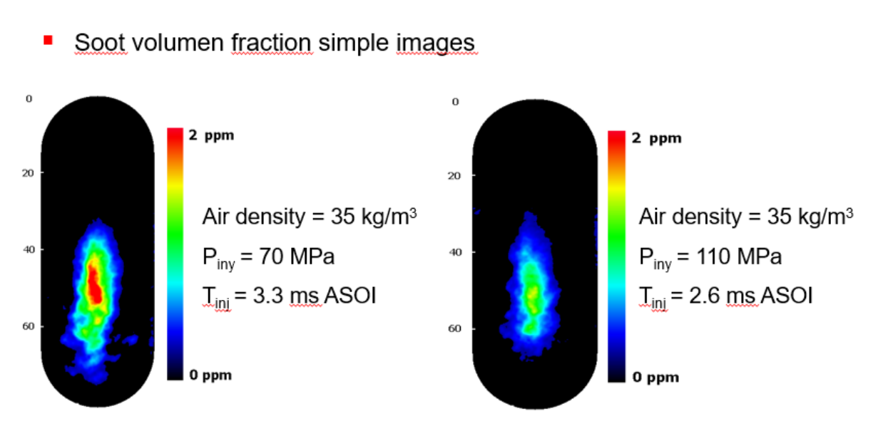
Examples of results obtained using the Laser Induced Incandescence (LII) technique
- Volumetric fraction of soot present in the flame for different injection pressures and time elapsed after the start of injection (ASOI)
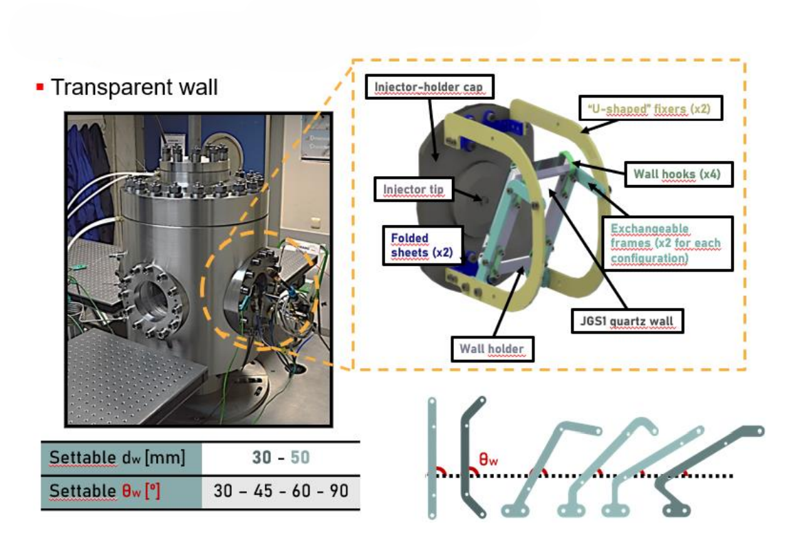
Main features
- Use of transparent wall to study the impact of the spray on the wall
- Versatile installation with the possibility of changing the angle of the wall and therefore the interaction between the spray and the wall
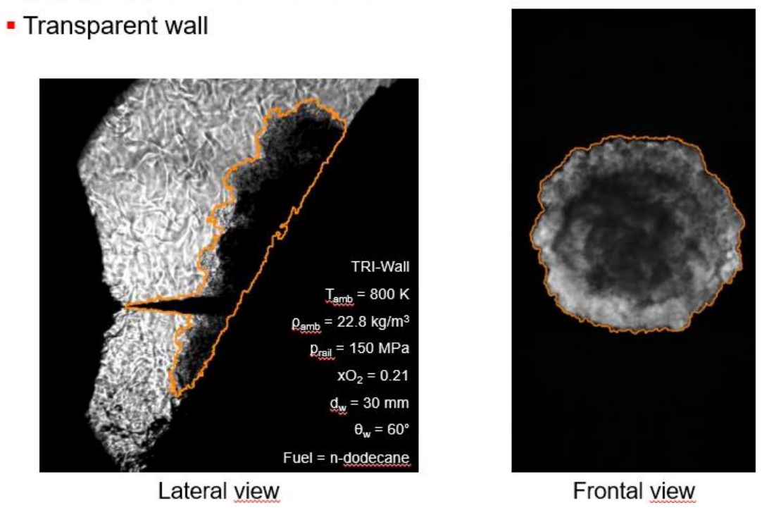
Samples of captured images
- Example of interaction between a dodecane spray and a wall positioned at an angle of inclination of 60º
- The left image shows the side view and the right image shows the front view captured thanks to the transparency of the wall
- The camera is located behind the wall and the wall is between the spray and the camera